
Building a surface
Triangulate points into ground you can contour, measure and stake from.
5 min read
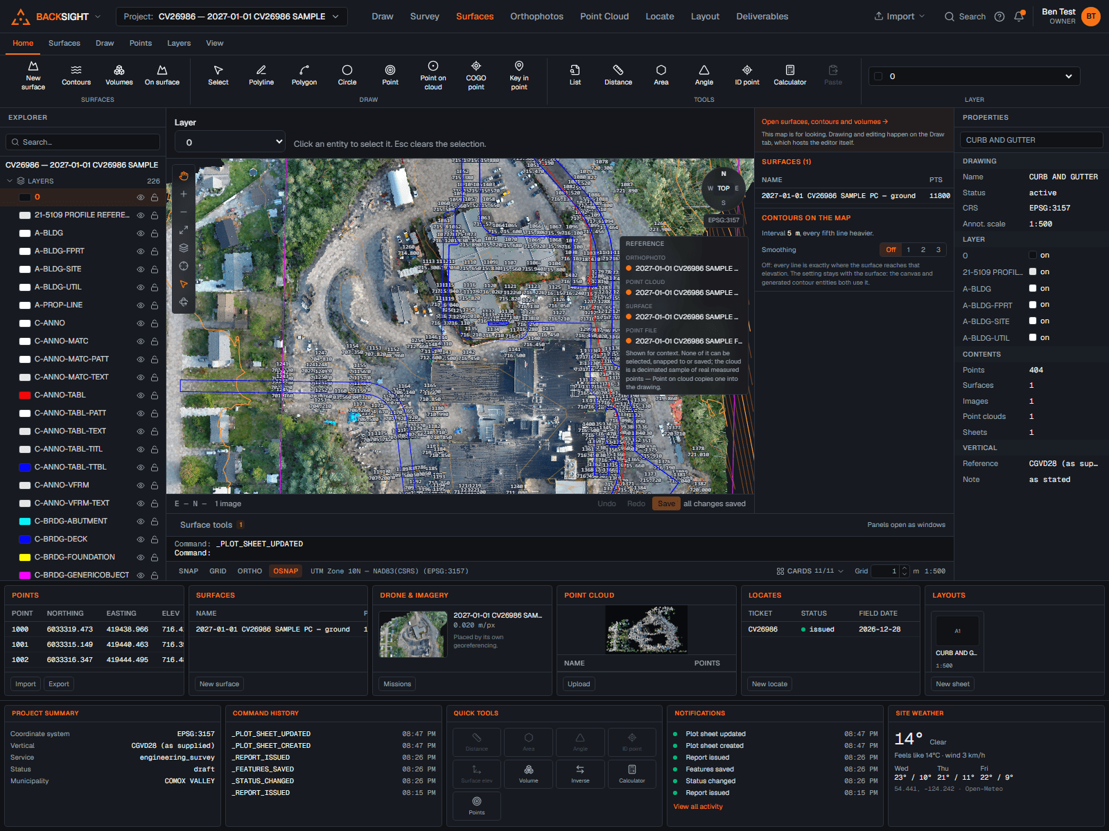
Where the points come from
- A point group you imported.
- Points and lines in the drawing.
- A point cloud, either its own ground classification, or ground Backsight classifies for you.
- A DEM raster you have brought in.
- A LandXML file somebody sent you, the design surface arrives whole, with its own triangulation.
Building from an imported point file
- Surfaces → New surface, and name it.
- Under “Points from”, choose the file under Imported point files. The drawing’s own layers are listed above it.
- State the vertical reference the heights are on, and build.
- The file is used on its own, not the file and the drawing's points together.
- Points in the file with no height are counted and reported, never assumed to be zero.
- Breaklines still come from a drawing layer, so check the linework covers the same ground as the file: a breakline reaching past the points is refused rather than extrapolated to.
Importing a LandXML surface
- Surfaces mode → New surface → Import a LandXML surface.
- Choose the file, name the surface, and state the vertical reference its heights are on.
- If the file holds more than one surface, pick which one, Backsight will not choose for you.
The file's own triangulation is kept
The faces in the file are used exactly as written, not rebuilt. That matters: re-triangulating the same points would ignore the breaklines the designer used, and the difference turns up in the volumes you get paid against. What you import is the surface the sender produced.
Units come from the file. LandXML states them, and the international foot and the US survey foot are different, about 10 mm over 5 km, so both are read and converted exactly. A file that states no units is refused rather than assumed to be metres. Faces the file marks invisible are holes it meant to leave, and they stay holes.
Careful
Nothing is reprojected. The coordinates are taken as being on your drawing's grid; if the file declares a coordinate system, it is reported so you can check the two agree before you build anything from it.
Exporting a surface
Every surface goes out whole, every vertex and every face, in metres on the drawing's grid, with heights as stored. Nothing is thinned or re-triangulated on the way out.
Export (top bar) → Surfaces, or the Surfaces card on the Deliverables tab, offers each surface two ways:
- LandXML TIN, the interchange every civil package reads; the surface arrives as a surface, ready for volumes and profiles.
- DXF 3D faces, one 3DFACE per triangle on a layer named for the surface, for a package with no LandXML reader or a client who asked for the TIN as a DXF.
Note
Neither format can carry a coordinate system. The LandXML names the system and vertical reference in its application note and the DXF in its opening comments, so whoever imports it can state the right one. Contours are different: draw them onto a layer from Surfaces → Contours, and they leave with the drawing as DXF or LandXML linework.
Building it
- Surfaces mode → New surface.
- Name it, and choose the source.
- Add breaklines: pick the lines that are real edges, curbs, ridges, ditch inverts, retaining walls.
- Add a boundary if the surface should stop somewhere definite.
- Build. You get the triangulation, the point and triangle counts, the plan area and the elevation range.
Breaklines are the difference between a surface and a guess
They are enforced, not suggested: a triangle edge follows every breakline you give it, so a ridge stays a ridge and a curb does not get triangulated across.
Gaps in the data
A triangulation covers everything inside its outer boundary, so a treed strip, a building footprint or a scan shadow is bridged by long triangles over ground nobody measured. Name the longest triangle you will accept and choose what happens there: leave the gaps open, and an elevation inside one returns nothing rather than a guess, or fill them, and the filled area is recorded on the surface, shown beside its area as a percentage, and stated wherever the surface is used. Leave the span blank and the surface behaves as it always has, bridging everything.
Checking it before you trust it
Surface check answers the first question a surveyor asks about any surface.
- Surfaces → Check against points.
- Choose the surface and paste your check shots, label, easting, northing, elevation.
- Check. You get the residual at every point: surveyed minus surface.
- Points outside the surface are reported as outside rather than interpolated to a number.
Read next
- Contours, spot elevations and slope labelsGet contours onto the drawing, label them, and read elevations off the surface.
- Volumes: against a datum and between two surfacesExact prismatic volumes, with the method and the area stated so the number can be checked.
- Point clouds: reading, clipping and thinningUpload LAS, LAZ, E57, PLY or XYZ/PTS, see what is in it, and cut it down to the part you care about.
Something here wrong or missing? Tell us and we will fix it.